An overhead-lifting device, such as chain falls engine
hoist, or cable come-a-long, can be used to lift the cen-
ter section of the hitch in place. Lower a loop of rope
or chain through the 4” hole in the truck bed oor and
attach it to the latch pin in the round hitch receiver tube
in the center section. Use the lifting device to raise the
center section until the round hitch receiver tube that
protrudes from the center section ts in the 4” hole in
the truck bed oor. Maintaining upward pressure may
facilitate fastening the crossmember to the center sec-
tion, especially if the truck bed oor has been distorted
downward from heavy use. If you use an overhead-lifting
device, it should be disconnected before squaring the
center section across the frame, installing the sideplates
and torquing fasteners.
Most trucks have FUEL LINES and/or BRAKE LINES and/or ELECTRICAL WIRES located along the frame rails
where B&W Turnoverball™ hitches install. Carefully Examine the location of fuel lines, brake lines and electrical
wires BEFORE INSTALLATION. Be certain you will not damage fuel lines, brake lines or electrical wires when
positioning hitch components, drilling holes, tightening fasteners, and lifting and lowering the truck bed. The
fuel tank vent, located on top of the gas tank, can be easily damaged during the installation of the hitch com-
ponents. Care must be taken when positioning the front crossmember and center section components.
On short bed trucks, BEFORE INSTALLING THIS HITCH, check for adequate turning clearance between the
front of all of your trailers and the truck cab.
DO NOT invert the ball in the socket when carrying heavy loads on 2 wheel drive trucks. The ball may hit the
top of the differential. Remove the ball from the socket before loading. A plug for the socket is available from
B&W.
Warning
WARNING
Warning
OVERHEAD LIFTING DEVICE
BEFORE INSTALLING
Ford (1980 - 1996)
3/4 & 1 Ton No Overload Springs
Ford (1997 - 1998)
3/4 & 1 Ton Trucks
Old Body Style and No Overload Springs
Ford (1980 - 1996)
3/4 & 1 Ton Trucks
with overload springs
Ford (1997 - 1998)
3/4 & 1 Ton Trucks
Old Body Style and With Overload Springs
Ford (1980 - 1996)
1/2 Ton Trucks
Model 1100R-1110R-1150R
Turnoverball
TM
Gooseneck Hitch Installation Instructions
B&W Trailer Hitches
1216 HWY 224 / PO Box 186
Humboldt, KS 66748
620.473.3664
800.248.6564
Fax:620.473.3766
www.turnoverball.com
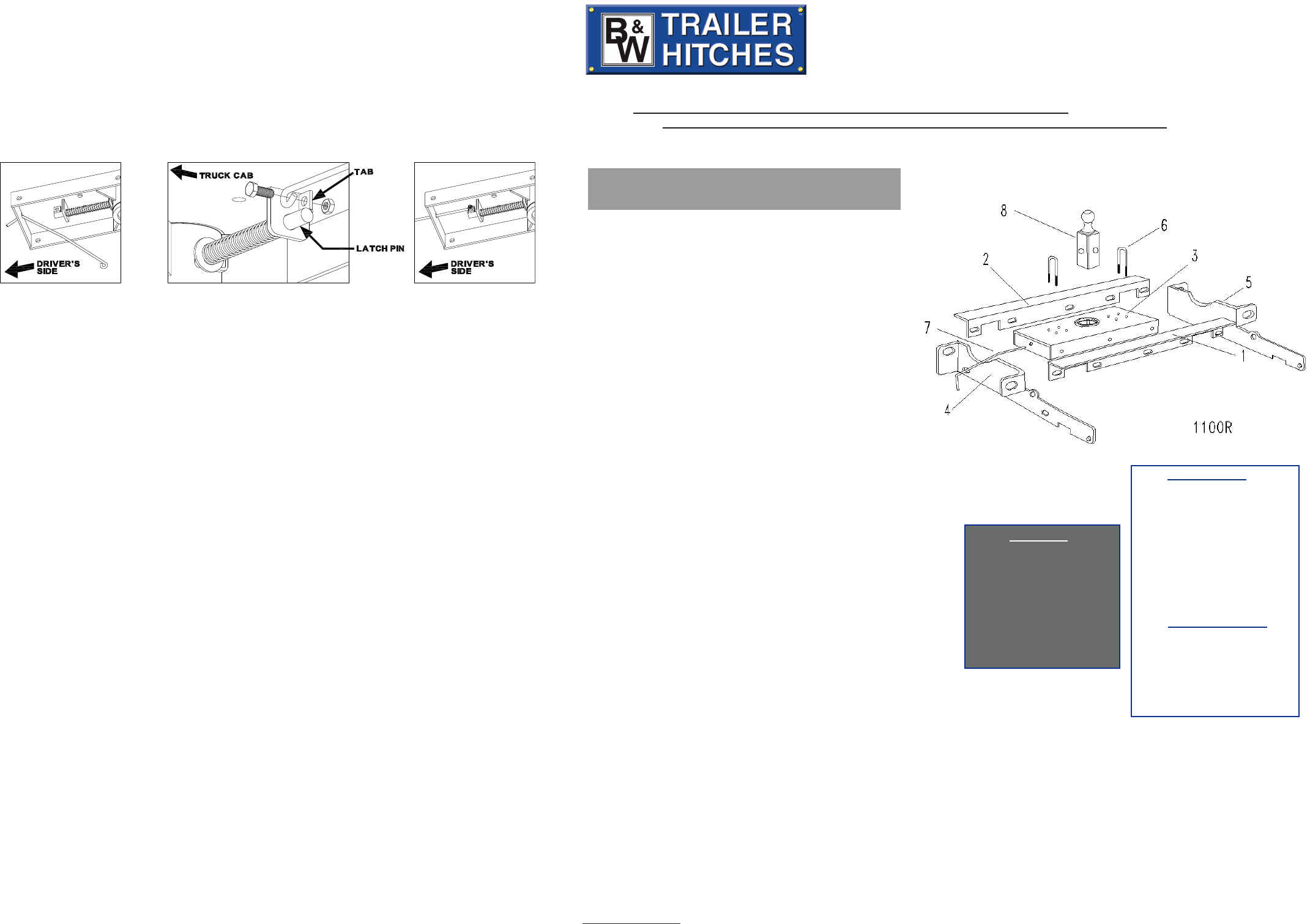
Parts List
1 - Rear Crossmember
2 - Front Crossmember
3 - Center Section
4 - Drivers sideplate
5 - Passengers sideplate
6 - Safety Chain U-Bolts
7 - Latch Pin Handle
8 - 2-5/16” Ball
12 ea. - 1/2” X 1 1/2” bolts
18 ea. - 1/2” at washers
12 ea. - 1/2” lock washers
12 ea. - 1/2” hex nuts
2 ea. - 1” X 2 1/2” CS
2 ea. - 1” hex nuts
2 ea. - 1” at washers
2 ea. - 1” lock washers
2 ea. - 1/2” X 2” X 2” spacers
Safety Chain Kit
2 ea. - 1/2” U-bolts
4 ea. - 1/2” lock nuts
4 ea. - springs
1 ea. - 3/8”x3/4” Bolt
1 ea. - 3/8” Lock nut
Mounting Kit
Call or Email us for Installation Support
Retract the latch pin by pulling the handle out until it stops and then rotating it. Place the 2-5/16”
ball (8) in the hitch receiver. Engage the latch pin by rotating the handle. Be certain the latch pin
passes through the holes in the 2-5/16” ball and fully engages through the hitch receiver. Repeat
this process with the 2-5/16” ball in all eight positions. Grease the square base of the 2-5/16” ball.
STEP NINE
STEP TEN
Copyright 2011
B&W Custom Truck Beds, Inc.
ALL RIGHTS RESERVED
1100R - 04 19 2011
INSTALL LATCH PIN RELEASE HANDLE
WARNING: LATCH PIN WILL NOT FUNCTION PROPERLY IF HANDLE IS NOT INSTALLED CORRECTLY.
Install the handle from underneath the truck by inserting it through the slot in the end of the center section
toward the driver’s side rear tire as shown. Attach the handle to the latch pin as shown with the handle on the
“cab side” of the square tab welded to the pin. The head of the bolt must be on the handle side, and the lock
nut must be on the tab side. The tab is welded to the pin in an offset position so that the handle will be lined
up over the center of the pin. If the handle is fastened to the other side of the tab, the handle will not function
properly. When installed
correctly the latch pin
may be disengaged
from the ball by pulling
on the handle from the
driver’s side wheel well
and rotating the handle
clockwise.
NOTE: We recommend reading instructions before beginning the installation.
WARNING: The tow vehicle’s towing capacities should under NO circumstances be exceeded.
 (2 pages)
 Manymanuals.com
 Manymanuals.de
 Manymanuals.fr
 Manymanuals.it
 Manymanuals.pl
 Manymanuals.cz
 Manymanuals.es
 Manymanuals-pt.com
Commentaires sur ces manuels